Category Archives: Programming

Animating on uneven surfaces

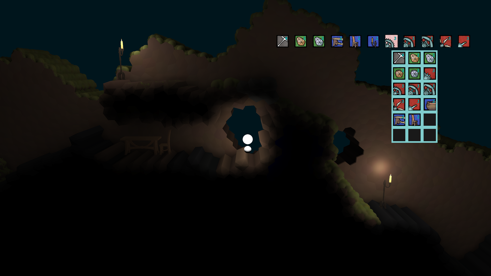
One of the looming technical challenges in Sun Shy is getting a character to look right as they run and jump around. For most of our game’s development, our character has looked like this:

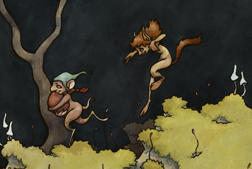
We’ve known for a while what we want our characters to look like – the player character of Sun Shy is to be a long-legged satyr-looking biped creature. Here’s some very old concept art from Halley that gives a bit of the vibe:

As a programmer with no artistic skills, I consider artists to be wizards of some kind, so I feel a lot of trust has been placed in me when I’m trying to recreate something like the above feel with code. There are various stylistic choices that can be made to make this kind of thing easier – give your characters short legs and take very fast, short steps, for instance, or giving them feet with no legs (like Rayman). These are/were all certainly options, but thanks to the support of Creative Victoria I have time to try doing it the hard way.

This post is a long one, and I don’t even really get to the bottom of it here. I’m sure I’ll be talking about animation-related things again in the future.

A note about game design philosophy

One part of this process is something we consider non-negotiable – visuals are in service to gameplay, not the other way around. We tuned the player controls so that they feel right before we started thinking about animation, and if it turns out that the way the player controls is impossible to animate without it looking goofy, we’re going to have a goofy-looking game and that’s just the way it is. At no point will we allow any of the systems mentioned in this blog post feed values back into player movement. This is mostly a game design thing – if the player wants their character to do something, but the character can’t do it because their feet aren’t in the right place, and the positioning of their feet is controlled not by the player but by our animation code, that’s not fair to the player. Also, what feels right and what looks right aren’t necessarily the same, and given the kind of game we’re making, the first one wins. I’m not trying to impose this rule on all game developers everywhere, and there have been some pretty notable games that go the other way (the movement in the old Prince of Persia games was animation-driven and worked pretty well, for instance), but it’s how we’re doing Sun Shy, and probably how all Snake Hill games will be done in future.

There’s also a technical reason for this. The systems described below can be expensive, and we want to be able to turn them down or off if necessary. Not just in a ‘turn down the graphics settings’ kind of way – if there are a hundred entities walking around, and only three of them are on screen, we want to only do the complex footfall calculations for the three that are visible, and we don’t want that change to affect movement. It also means in networked situations, the client can do their own local footfall calculations rather than needing to sync it over the network.

Inverse kinematics and foot placement

There are two parts to this problem – where to put the feet at any given time, and having done that, how to draw the leg. The second problem is solved with something called Inverse Kinematics, often abbreviated to IK. Today I’m just going to be talking about foot placement, because the IK part of this took place outside the Creative Victoria research. It does have a few interesting things to be said about it, though, especially because the creatures we’re animating here have two knees per leg – I’ll be writing a blog post about this later on.

A straightforward attempt at foot placement

The first attempt we made to have feet get placed coherently was vaguely inspired by David Rosen’s GDC talk about procedural animation in Overgrowth. (I say vaguely, because they’re really not terribly similar, and I don’t want to implicate David in the fact that this technique didn’t work for us.) Our plan was essentially to create an ellipse, roughly where the player’s feet should be, and move two feet around that ellipse. We would then do a ray cast straight from the player’s hip to the current foot location, and if it hit something, place the foot there.

This method was initially quite promising. The foot isn’t really planted, so this system doesn’t guarantee a lack of foot skate, but if you base the rotation rate of the ellipse on the horizontal velocity of the character you can make it look pretty convincing. It even looked pretty good while the player was airborne without any further work – they’d kind of flail around in the air, but while it looked a bit comical, it was okay, and mostly not broken.

Endearing, but kind of dodgy. Any initial promise this showed didn’t really materialise when we tried to polish it, though.

The problem proved to be the ‘mostly’. The last 10% of quality here was elusive – sometimes foot skate reared its head, so we made a system to actually lock the feet to world space when they hit something, then lerp them back to the ellipse when they stopped hitting something. That ended up having feet sometimes get located weirdly up on ledges when the player was running towards a step and then stopped at the last minute. We also needed to do some raycasts to determine where the centre of the foot ellipse should be, and then some smoothing of those values so it wouldn’t pop when the player walked over a ledge.

Ultimately the system became incomprehensible. I ended up with variable names like footGroundedHeightSmoothedFudgeMultiplier, and trying to fix a given problem involved way too much trial and error. Worse, fixing one problem would often break something else. In other words, all the problems that usually come up with badly written code. This is what inspired the next attempt – a system that, whether or not it works, might at least make sense to me rather than being a bunch of hacks hanging together in strange equilibrium.

The Analytical Approach

So, what’s the opposite of the above ‘make something up and hope it looks kind of good’ approach? Simulate everything! You can probably guess from the number of subheadings that this is the approach that eventually worked, or at least currently shows the most promise. Mentally, I broke this part of the task up into three sections:

  • When a given foot should start a step (timing)
  • Where that foot should be stepping to (foot placement)
  • How it’s going to get there (stride shape)

I won’t be going through these in turn, because it’s not the order I actually solved things in the end.

Stride shape

The shape a footstep takes is probably the least analytical part of the process. Basically, it’s a spline – the foot moves along it. Formally, it’s a cubic Bézier spline – the same things that you draw with in vector art programs. This isn’t even remotely based on a physical system. This kind of spline has four control points – the first and last will be the location the foot is coming from and the location the foot is targeting, and the second and third will determine the shape it follows to get there. So far we have adjusted this basically by eye, and it’s been okay, but it’s a future target for tweaking to make things look nicer after other parts of the rendering (such as bringing in actual skinned character meshes) have been polished.

Using splines here has a few major advantages. Splines are very predictable – we can decide exactly how long we’re going to take to traverse the spline, and then ensure that it happens, by simply ticking our T value appropriately. This means we can look ahead and say “We need this foot to be at this location exactly this many frames in the future”, and it will definitely happen. Somewhat more complicatedly, it also allows for retargeting of a step – we can get the parametric form of a spline and take its derivative to get its velocity at any point. This means that if the player is half way through a step and they need to put their foot somewhere else instead, we can create a new spline from the current position to the new target without any discontinuities in velocity or position (which looks unnatural)

Foot Placement

This turned out to be one of the biggest, trickiest parts, but it also has some of the most actionable advice for anyone out there attempting a similar system. That advice is: Prediction is king.

Our initial plan involved predicting where the player would be by using simple dead reckoning – that is, we just take the character’s position and velocity, and if we want to know where they’ll be in n seconds, we assume it will be currentPosition + currentVelocity * n. This will be accurate assuming our velocity stays constant

Because we’re using splines for our stride shape, we can dictate exactly how long a given stride is going to take – so when a foot determines that it needs to initiate a step, we know exactly how far in the future it’s going to land. So we simply predict where we’re going to be at that time, and do some raytraces down from there to find an appropriate target for the foot to plant. This is going to be great.

Turns out, it isn’t great, because dead reckoning sucks. Behold:

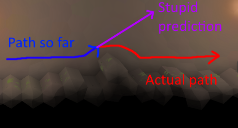
Essentially, any time our character would have a path that wasn’t totally linear, such as running over a bump, the system might fail badly. Any time it happened to initiate a foot step while on the upward step of a bump, it would say to itself “Well, where am I going to be when this foot needs to land… IN THE SKY APPARENTLY” and then start flailing as though it had just run off a cliff (I regret that I didn’t save any gifs from this period, and I’m too lazy to go back through version control history for them, but it was mostly less hilarious and more just broken-looking).

Biting the prediction bullet

It became apparent that we were going to have to do this properly. We were going to have to simulate ahead of time where our player’s character is going.

At this point, I realised there wasn’t anything in between the half-arsed ‘project velocity forward’ method, and a complete ‘predict by simulating the player’s movement for a little while into the future’ solution, so that’s what needed to happen. This seems like it would be straightforward – or rather, it seems like something your engine would do for you, so you wouldn’t have to worry about it. Unfortunately, that’s probably not true.

The reason it’s not always true is that physics engines don’t always let you say “Hey, this one single rigid body, could you simulate it in isolation for a few seconds, then throw all that information away and go back to the current frame”. For instance, I believe Unity has a function Physics.Simulate() that allows you to look ahead, but you can only do this for the entire world, not a single object. I believe Box2D could be persuaded to do something similar, but I think this would only be acceptable for a relatively simple game (in terms of physical complexity) – Sun Shy can easily have dozens or hundreds of rigid bodies present, and thousands of pieces of static collision geometry, so I don’t think this would be very feasible.

This leaves us with the not-terribly-fun option of recreating a simplified version of our own physics engine so we can run our own look-ahead simulation each frame. Remember that this doesn’t have to be perfect – and indeed, it can’t be because the look-ahead can’t know what the player will input. In our case, we have to reproduce simple physics, as well as the scripted game entity behaviour described above (the circle cast down and the foot spring and all that). Simple physics is done something like this:

position += velocity * deltaTime;

velocity += force * deltaTime / mass;

The force comes from gravity and whatever controller forces we have cooked up. Proper physics people call the above technique ‘Euler integration’, aka the least accurate kind of integration, but for our purposes it’s acceptable.

We also have to attempt to reproduce collision response. This is a bit hairy, but bear in mind that we can still use our physics engine’s collision query, we just can’t simulate – so we can check if a collision will occur in the future, and just cancel the velocity in the direction of the collision normal by using vector projection. This isn’t perfectly identical to what the physics would do for collision response, but in practice it turned out to be okay.

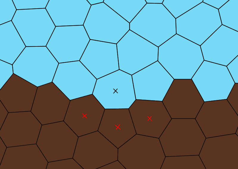
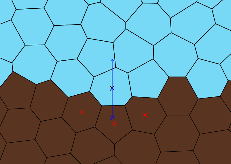
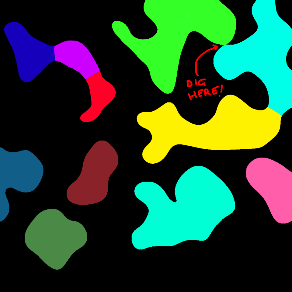
It turned out to be invaluable for tweaking this mini-simulation to draw the line of predicted positions, as well as kind of reverse-breadcrumbs every ten frames or so to show where the player is predicted to be at frame 10, 20, etc. In theory, if you get things perfect, the circles should be stationary except when something unexpected happens (like the player jumps or changes input direction).

Note that the blue bits of the line correspond to the points in the prediction when the player’s ‘foot’ is touching the ground, and the red parts are parts when the player is predicted to be airborne. This turns out to be helpful later on.

Also, note that this prediction isn’t cached in some fancy way – we’re calculating about sixty frames into the future, then throwing it away and redoing it, every frame.

Footfall placement for ‘free’

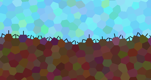
Now that we’re basically running a mini local version of the player update step to predict the player position, it turns out we get something else of value here. Our player update step involves circle casts downwards to look for a base of support – so in addition to our array of future positions, we can record an array of future support locations. We can use these as potential places to put our character’s feet! Even better, these positions have the following advantages:

  • Already calculated
  • Definitely correspond to where the player is standing and has a sensible place to put their feet – it won’t report a footfall location at the bottom of a narrow gap or something like that.
  • Tends to favour high or upward-facing surfaces, as feet usually would.
  • Comes complete with surface normals, so we can look for more suitable options based on surface orientation.

Visualised, here’s what our footfall predictions end up looking like:

Not actually for free, though

Not so surprisingly, there’s a little bit more work to do here.

Look at that last gif. If we took the next two yellow circles as the timing for our next steps, and the corresponding furry yellow normals as the place to place the foot, we’d be in reasonably good shape, right? But look closely. Unfortunately, this isn’t possible – and worse, it’s impossible for a somewhat unfixable reason. The yellow circles happen at evenly spaced intervals in the future, and sometimes, those intervals happen when they player is airborne. Sometimes we’re properly airborne – like, we’ve run off a cliff or jumped or something – but other times, it’s just a slight hiccup in the shape of the ground we’re running across, so there’s nowhere to place your foot for a bit. So, what do we do?

The way I’ve gone here is to take the yellow circles as a place to start searching in our prediction array. Searching back from that point suggests taking a short step – like how you might take a shuffling step or two if you’re running up to an edge you have to jump off, just so you have your strong foot land just on the edge. Searching forward in the array corresponds to delaying the step. This is more ‘dangerous’ because if we delay a step too long, it can look unrealistic – anyone can take arbitrarily short steps, but as steps get longer they start to look physically impossible. Ultimately I ended up searching backwards about five frames and forwards up to about eight, but these values will vary wildly for different implementations.

I did a lot of experimenting here to get things to look right, and if I tried to recount every detail I’d never finish this article. However, there are two pieces of information I came away with that I can share to save some time for anyone attempting something similar:

  • If you have to shorten or lengthen one step, you shouldn’t have that affect the timing of the steps after it. It seems logical to do this (ie the next step happens three frames early, so subsequent steps will all happen three frames early to keep the timing right), and not doing it will mean a short step tends to get followed by a long step. I think that’s just how bipeds work. I’m no animator, so I can’t fully justify this, but delaying subsequent steps when you take a long step just made things look off to me, in a way that was immediately fixed when I removed that feature.
  • When you’re searching for an ‘ideal’ foot placement, it can be good to have a scoring system, where you award a footstep candidate ‘points’ for things. The system I used awarded points for being close to the ideal timing (the yellow circle), for the normal was facing more upwards, and for being physically higher up. This effectively caused footfalls to favour the tops of rocks and other obstacles. If you character runs up and down smooth slopes, though, you might want to de-emphasise the favouring of high ground.

With that all put together, here’s a visualisation of the strides themselves. The actual control points can be kind of made up. There are a few tweaks I gave mine, the subject of another post perhaps, but it’s mostly just taking a pre-built roughly square shape and shearing/scaling it to fit the vector from the foot origin to the foot target.

So now, we can add actual foot steps! This is where our previously mentioned inverse kinematics setup can finally show itself.

Suddenly it looks like a creature! This was the first time I really thought this might be doable, and I can’t fully describe what a relief that was.

Getting airborne

This is, for a nice change, relatively straightforward. When the player is in flight, I simply positioned their feet on the outside of a circle below their centre of mass, with the angle determined by their direction of velocity. We then squash the circle to make it an ellipse, and that’s it! The maths looks like this:

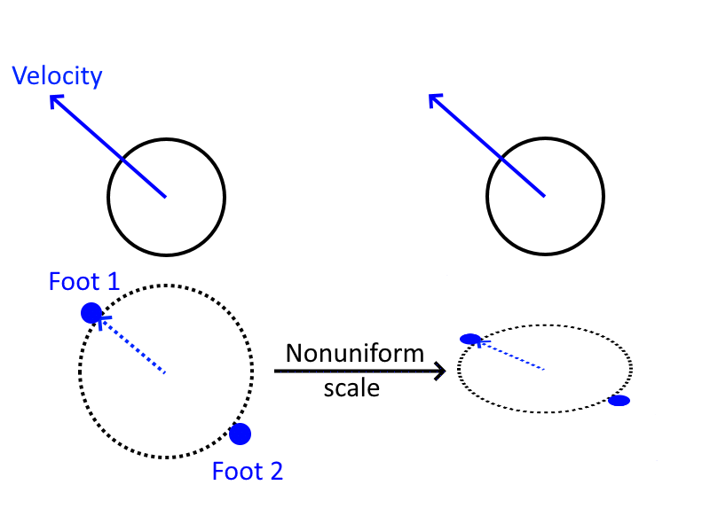
And the results look like this:

We want to scale and cap the magnitude of the velocity here so that our feet don’t end up in crazy locations when the player is falling very fast, too. There are lots of things that require you to basically mess with numbers ‘to taste’ when you’re doing what is effectively procedural art, and this is one of them.

This brings us to the next logical step, which is transitioning between running and being airborne (and vice versa). This is roughly the current stage of my research. By predicting future footfalls, we can actually get most of the way there fairly easily – detecting being airborne is simply a matter of noticing when the system can’t find any appropriate foot placements for a given foot. If that happens, I simply interpolate from the current foot position to the elliptical airborne foot positions, as described above. In the other direction, as soon as the system does detect a foot placement again, that means we’re about to land, so we start stepping towards that point. So long as we set up our stride spline so its initial velocity matches our character’s flight velocity, the transition is smooth – again, more on that in a different post.

So that brings us to the current ‘state of the art’, as it were – our best bipedal character, running a little obstacle course I put together. Note that this entire animation is the result of just running to the left – we’re not jumping or anything here.

My personal verdict? I think this is getting there. It’s not perfect, but for situations that are basically describable as ‘running along flat-ish ground and occasionally going over a drop off’, I think it’s pretty solid. At this point, while there are a few features still to add, I’m going to come back to tweaking after we have character models in and I can get a good look at a more final version to judge what needs to be done.

Lies, Damn Lies, and Tech Demos

It pays to be careful of articles like this. If you’ve ever had the experience of trying to implement a game-related algorithm based on a whitepaper or similar thing, you’ve probably had the experience of learning that actually there are huge, gaping flaws in the technique that the author conveniently neglected to mention. Even as someone who plays games and follows early press for games with cool new tech in them, you’ve probably felt that sting of noticing that things were a little on the optimistic side when they were presented at E3 (or whatever). With that in mind, there are a few things I should mention about the above techniques.

This isn’t a perfectly complete guide

I’m not confident that many people really read all the way through this kind of blog post, and I’m even less confident that anyone is going to sit down and actually implement this from start to finish. But if I’m wrong about this, and that enthusiastic person is you, be aware: Putting this technique in your game will be an adventure. This post is already way too long, and I’m not a good enough writer to fully elucidate every little detail that went into this experimentation without writing a lot more (which I hopefully eventually will). Getting this right – or at least, as right as it currently is – has been one of the more challenging pieces of development in Sun Shy so far, and I can’t really recommending attempting it if you’re not up for a bit of experimentation.

The algorithm isn’t perfectly complete yet either

There are a few situations that this doesn’t yet handle, which I’ve kind of glossed over. Our character doesn’t handle disappearing or moving foot supports yet (if, for instance, they dig out from under their own feet). Our character sometimes looks a bit weird when they turn around and change direction. We haven’t handled jumping yet. We sometimes get some weird leg shenanigans when the character lands from a high jump, or runs up a steep slope.

I’m about 80% confident that, when all is said and done, and we have a much more tweaked version of this, it will look good about 98% of the time. That last gif is an honest one – that’s how it looks when it runs situations that it has already been designed to handle, and I think it looks pretty good – when we have real character art, I think it will be pretty sweet. However, I don’t want to pretend that the algorithm never does something that looks a bit weird, nor am I certain that all those situations can be stamped out by the final release. I’ll definitely be posting more about this as I keep working on it.

Coming up next…

These last four posts have been so tightly packed because I’m terrible about procrastinating about blogging, and these represent the bulk of the research worth writing about for (my part of) the Creative Victoria project. So the next post probably won’t come in the next couple of days, but I do intend for there to be another one.

I still haven’t talked about how three-section inverse kinematics works, and I glossed over a lot of the details of using splines for stride shape – especially the bits about deciding the shape, and calculating exact velocities to get continuous motion on the feet when you have to interrupt a step. I also didn’t really talk about retargeting steps, because figuring out how to get that to look good is an ongoing process – it’s definitely necessary, though, because the best motion-prediction algorithm still can’t always guess when the player is going to change direction. I’m also going to have to talk a bit about standing still, changing direction, and eventually, dealing with situations like fighting or taking damage. So, file this under ‘ongoing research’. But it’s been a lot of fun to work on, and I’m mostly optimistic about the tasks ahead.

Classifying Sun Shy’s Environments, Part 2

The last post was about classifying areas inside caves as rooms, where the joins between the rooms were, and where we might spawn game features such as loot, boss fights, or NPC dwellings and the like. All our examples were based on an abstract shape, though, which was rather smooth. Notably, unlike any surfaces in Sun Shy. However, this is not a problem limited to Sun Shy – any game world with a grid of any kind, including oldschool 2D games with bitmap-based destructible terrain (like Worms), can potentially suffer from this problem.

A quick recap. Have a look at this image:

This is roughly what a ‘flat’ piece of ground looks like in Sun Shy. Because of the irregular grid, this is as flat as it gets. This is an area that we might hope to identify as flat ground, that a player might walk across. They certainly can walk across it – the control system described here allows it – but let’s look at the naïvely calculated normals:

These normals are all over the place – occasionally one points straight up, but lots of them are pointing in weird directions. We need a way of smoothing them out, to get the broad sense of the direction of the surface.

In the case of Sun Shy, it makes sense to look at the ‘normals’ for the tiles, rather than the boundaries between the tiles (for most purposes, the tiles are the things that have information attached to them, so this is useful for navigation markup and the like). If it sounds like nonsense to have a normal associated with a tile centre, that’s because mathematically it is – but, let’s go with it for now.

Here’s a zoomed in section of the above Voronoi tessellation.

We’re going to calculate the ‘normal’ for the tile right there in the middle. We’re going to do it by looking at the centre point of every neighbouring tile that has dirt in it, here noted in red:

We then calculate the average position of those neighbours, and draw a line from that average position, through the centre of our main tile. That’s our tile normal!

As we can see here, this is a pretty good result – if we apply the same approach to all the empty tiles here that are next to filled tiles, we see things are looking pretty good:

Looking pretty good, but not perfect. After all, this is as flat a surface as the tile grid can possibly provide – we should be able to recognise it as such, in spite of some inevitable lumps. To solve this, I’ve simply averaged the normals of every tile with its direct neighbours. Instead of drawing another version of the above diagram, I’ll show this in action in Sun Shy.

Seen here with blue lines representing the initially calculated normals. I know the colour makes this hard to see – you can get a higher resolution version by opening the image in a new tab.
Seen here with red lines representing the smoothed normals.

Although we’re never going to get the normals uniformly pointing straight up, here, I think they’re looking pretty good – those red lines pointing upwards come close enough to representing what I would intuitively call the direction of the walls/floor/ceiling.

From here, it should be pretty straightforward to grab adjacent tiles with a sufficiently upward-pointing normal to define a floor area, which gets us the rest of the way we need to classifying the rooms from the previous post as walkable or not.

What about games that aren’t Sun Shy?

Indeed, the big point of this work has been to find techniques that can be applied outside of Sun Shy, and this post has mostly been specific to Sun Shy’s irregular grid set up, which pretty much nobody every uses. This technique actually has some value in unexpected places, though.

If you’re making a square grid game, you’re not going to have any trouble identifying floors or ceilings or walls – those directions can be represented on a square grid perfectly. However, sometimes you want to recognise other patterns, especially if your tiles are very small – for instance, the size of a single pixel. Let’s say you’re making a worms-style game – tiles get dug out by explosions, and when that happens you simply have a big 2D array of booleans that has a circular chunk cut out of it, like this:

Naturally, detecting collisions with this is no problem – you take a position, look up to see if that ‘pixel’ is black, if it is, that’s a collision. Easy! But what if you want one of your weapons to be, say, a laser cannon that reflects off what it hits. (A better example is probably a grenade that bounces around, but I don’t have the parabola drawing skills for that.) So you want it to do something like this:

How do we do that? Clearly, we need a surface normal, but the actual ‘geometry’ only has vertical and horizontal edges. That’s where (a modified version of) the above algorithm can save us. What we need is to take a box of pixels around the pixel we’ve collided with. Within that box, we’re going to obtain the average location of all the black pixels, and the average location of all the white pixels. Then, we simply draw a vector from the average black pixel position to the average white pixel position, normalise it, and that’s our surface normal.

It should be noted that if you’re looking for anything mathematically correct, you probably shouldn’t be using a grid of bools for your collision system. But if you just want things to look reasonably decent, this system works quite well. The bigger the box you use to average the pixels, the more broad patterns this will pick up on, and the more finer detail will get lost. It’s also possible to precompute the normals of a shape like this, and only update areas that get affected – this could speed things up a lot if you’re doing a large number of collision checks every frame (for instance, if you have lots of particles that are bouncing around in the environment).

Note that you do need to check for a broken case here – if you have, for instance, a collision grid that is organised like a checkerboard for some reason, and your box is an odd number of pixels wide/high, this technique will cause a divide by zero error when you try to normalise the vector at the end. There are other situations where this could conceivably happen, but only cases where there’s no good value for the normal anyway. Even so, if it somehow comes up, better to have some weird normal calculated than throwing an exception or crashing.

Next time…

The last big piece of research I carried out was about getting a character to animate convincingly on irregular surfaces. This one got complicated. I’ll be writing a bunch more about that soon.

Classifying Sun Shy’s Environments

A big part of making a procedural environment is coming up with the shape of the world. There are lots of ways of doing this, from using Perlin noise to make a mountain range to simulating plate tectonics for continents and island chains. This article is about the step that comes after that.

Say you use a fairly well-trodden algorithm to generate a cave system – there are lots of articles around for using Perlin noise as a basis for this – and now you have a cool area to explore. If you’re making a game about exploring a completely inorganic and empty cave system, that’s all you need. But, what if you want there to be a bit more life in these caves? What if you want there to be creatures building homes in them, or big spacious areas with monsters in them guarding treasure?

We could approach this from two directions – we could build the cave for the event, or we could build the event for the cave. Because we want to adapt to both procedural and player-created environments, we have chosen the latter approach. In other words, we’re creating the environment, then looking for places where a monster might want to build a home.

Of Tiles and Flood Fills

A theme that will recur a bit here is that of flood filling. This is usually thought of as a tool in a paint program – you get out the paint can tool and click somewhere, and that area gets filled with the selected colour. Specifically, ‘area’ here is defined as “everywhere you can reach from the originally clicked pixel, without stepping outside the originally clicked pixel’s colour”. I won’t spend much time talking about how this works – I assume most people are familiar.

So, suppose we have a world of tiles, every tile either blocked (with dirt or stone or whatever) or open (empty). We might want to find, for instance, areas that are completely unreachable to each other – ‘rooms’ of connected open tiles, that have no path between them and other such rooms. Hopefully, you can imagine that this is doable with a flood fill – if I gave you a bitmap that looks liked this:

With not too much time faffing about in a paint program, you could classify different rooms like this:

Now that we have that classification, what can we do with it? Well as it stands, not a great deal – it’s nice to know that the orange room and the green room can’t touch each other, I suppose. But there’s nothing here to tell us that that big orange room is actually kind of a couple of distinct areas – meanwhile the light blue and the orange room, if you could just dig a little hole there, could be joined.

Of Distance Fields and Dijkstra’s

A good thing to know about if you’re a game developer is Dijsktra’s algorithm. It’s conceptually related to the idea of flood fills, and in some cases it’s just a slower version of A* search, but it let’s you do something kind of cool. Instead of finding a path from a point to a point, it lets you find the optimal path from every point to a point. This can be handy if you have, say, a horde of enemies all chasing a single player. It does this by creating a sort of expanding frontier, starting from a given point, and as it grows outwards it records the shortest path from the starting point to every point it reaches. However, there’s no reason it has to start from a point – you can always start Dijkstra’s from multiple points, to generate (for instance) a map of shortest paths to the nearest health pickup spawn point, or whatever. Seriously, it has a lot of potential uses – if you’re a game developer, I recommend having a good look at the wikipedia page for it if you’re unfamiliar.

In this case, we’re going to use this mutated version of Dijkstra’s to find a map that contains the shortest distance to a blocked tile, for every open tile. It will look something like this:

Now we’re getting somewhere. Since these examples are based on a random noise image, rather than actual screenshots from Sun Shy, it’s a bit less tile-based than the real situation. But, you can see here that the darkest grey areas are open tiles that are close to walls, etc. It turns out that this has a name, so instead of referring to this as a weird mutated Dijkstra’s search, we can call it a Grassfire transform, which sounds cooler anyway. As an aside, this is kind of related to the field of algorithms called Skeletonisation algorithms, and while that’s not exactly what we’re doing here, makes for interesting reading relating to procedural generation in general.

Room size and open spaces

Let’s have another look at that coloured diagram from above:

If we were looking for a a place to spawn an epic boss battle, what is the right place? We’re going to need a lot of space. A reasonable first thought would be to classify the rooms by area – simply counting up the pixels. Unfortunately, this method kind of sucks. I haven’t actually counted the pixels, but if we look at the above image, it looks to me like the orange room is the biggest one, and maybe it’s a good place for a boss fight but it isn’t enormously spacious at any point. The bluey-purple room in the top left has quite a few pixels, but is very skinny and has no high ceilings. The pink room is not huge, but it’s round and you could fit a larger thing in there. In general, the point here is that a long skinny area can have a lot of tiles in it, but it doesn’t really have a lot of room. A big monster can’t stand up in there, there’s not space to fly around, etc.

Now, let’s take another look at the grassfired version of the caves:

Now, we have a simple method of finding big open spaces – look for specks of white. Long skinny rooms end up mostly dark grey, because they’re not appropriate for boss fights (or whatever). The bigger our space requirements, the more iterations of our algorithm we can go through to ‘grow’ out from the walls.

Door ways and digging sites

Often, games need to be able to classify areas as discrete rooms. For instance, management games like Rimworld sometimes have to divide areas into rooms for things like whether a rotting corpse in the corridor should contribute to someone’s bad mood amount their bedroom decorations. Happily, these things are doable using the simple flood fill approach described above – simply count doors as walls for purposes of blocking the flood, and you’re good to go. However, when it comes to classifying places where creatures might like to build things, this doesn’t help us. We need to decide where to put the doors, rather than reacting to where the player puts them. So, what we’re going to do is the same old flood fill classification approach, but we’re only going to flood areas that are above a certain level of whiteness – that is, our flood fill won’t just be stopped by blocked tiles, it will also be blocked by tiles that are open but very dark. We get something like this:

We can see that most of the rooms are still considered a single room according to this approach, but the spindly formerly-purple room in the top left has been split into three small rooms, and the huge orange room is now considered two. Naturally, we could tweak the threshold of wall proximity (effectively, changing the grey darkness threshold for the flood fill to be blocked by) if we wanted to count bigger or smaller openings as doors.

Finally, we can re-flood from these colours, now getting all the open spaces. So long as we do all these flood fills in parallel, the distinct rooms’ colours will butt up against each other, showing us the place where a door should go:

A room-separating door could be placed anywhere that two non-black colours touch.

Finally, we can continue this flood fill a bit further, beyond the open tiles, and into the blocked tiles. If any differently coloured rooms touch during this stage, instead of finding a door, we’ve found a place where we can tunnel between the two rooms. The more steps we go through expanding in this way, the longer the tunnel is that we’ll have to dig. For instance, above, the cyan and bright green rooms are coming very close – if we expand outwards a little bit, this is what we find:

Note that we’re not really expanding these caves, this is all exploratory. What we’re actually going to end up with when this is all done is something like this:

Coming up next…

This is all well and good, but we’ve ignored a little thing called gravity. In other words, this all makes a lot of sense for a top-down 2D game, but we’re overlooking the fact that these rooms don’t necessarily work for a platformer, since the doors are in the ceiling and there’s no space to actually walk around. I’ll talk about how to do those things a bit in the next blog post.

Coming out of Hibernation

So it’s been quiet out here since my last post, almost two years ago, about finalising Sprite Lamp. One of the things I mentioned is how bad I am at interfacing with the world through social media, and I think my lengthy silence bears that out. However, some things are happening! And some of those things involve being a bit more talkative on the internet. So this is me trying to get back into the swing of things. Each of these things will be getting a Proper Post in the near future.

New game project

It’s been a while since I was working on Sprite Lamp full time, and we’ve been kicking around/playing with a few ideas for Snake Hill Games’ next project in the meantime. I don’t know how this goes for most developers, but for me, this process usually involves building a few demos or other bits and pieces, seeing what seems good and/or interesting, and eventually settling on something to focus on.

Long story short, we’ve settled on something. It’s called Sun Shy, and it’s getting to the point now where I should probably start talking about it in public. Soon (tomorrow), I’ll put up a big, proper post. For now, I’ll just say that we’re hoping it will appeal to people who enjoyed games such as Factorio, Terraria, and World of Goo (yes, I realise they are three very different games). We’ve been chipping away at bits of it for a good while now, but not full time and not consistently, so it’s still early days – I suppose I would say it’s part way between a fairly well-fleshed-out tech demo and a pre-alpha game. It’s quite tech-heavy, so there’ll be plenty to say about how we’ve been approaching various challenges in the game’s development.

It’s still Saturday in America, which I think means I have to post a screenshot.

A screenshot of a 2D platformer. The scene is mostly made up of dirt caves at night. Two candles on stands illuminate the environment. The main 'character' in the middle is a placeholder graphic of two spheres.

New team member

Snake Hill Games has historically consisted of two people. Sprite Lamp was developed mostly by me. Anyone who used it or saw anything about it will also have come across the artwork associated with it, such as that demo zombie, which was by Halley Orion. Since then, though, Snake Hill games has grown! A friend of mine by the name of Dr Ahmad Galea, hot on the heels of finishing his physics post-doc in the faraway land of Norway, has decided to join me in the exciting endeavour of game development. Sun Shy is going to be a bit heavy on simulation, and having Ahmad around to help me with the maths that I’m not up to is going to be great.

Creative Victoria

For those who don’t know, Snake Hill Games is in Victoria, which is a state in Australia. There’s a group called Creative Victoria that funds various arts stuff here, including research. Since games are a subset of art (apparently that discussion is finally settled), that means they fund games research. With this round, that includes us! The grants aren’t to work on a particular creative project, but the research can (obviously) have relevance to projects, and our research is about coming up with AI and animation techniques to deal with difficult 2D platformer environments. The animation stuff will mostly be about irregular environments (ie generated run cycles for bumpy floors, that kind of thing) and the AI stuff will mostly be about procedural and/or player-generated environments. You can read the announcement of the various funding recipients and their projects if you like.

Since it’s publicly funded research, of course, part of it is about contributing to a public knowledge base, so we’ll be documenting any useful techniques we find/develop here (as well as blogging about any pitfalls, false starts, and general failures on our part). More coming, on this front.

Website plans

I’m painfully aware that this website could in general stand to be improved . We don’t have a great deal of web development expertise between us right now here at Snake Hill Games, but since I’m going to have to post a lot more in the coming months, we intend to put our heads together and figure out how to make things at least a little bit nicer.

Multiple sprite sheets, Sprite Lamp, and Unity

So I mentioned yesterday that I’ve been working on a small tech demo in Unity, to help make sure I notice all the difficulties that can come up with Sprite Lamp, and the first one that has presented itself is the issue of animating with multiple (sets of) sprite sheets. A few people asked me about this already but I didn’t quite have my head in the game enough to give good answers. Hopefully now that I’ve played with it a bit more directly, I can do better.

Here’s the script referenced in this post.

Oh and before I go on, a quick annoying reminder that Sprite Lamp is at 30% off on Steam as I write this!

Animations with a single sprite sheet

The simple situation for frame animation in Unity is one big sprite sheet. This is, I suspect, reasonably common – especially with people working with pixel art, and textures going up to 4096×4096. Someone in this situation who wants to use Sprite Lamp is in a pretty easy situation in terms of programming – essentially, everything just works easily. You’ll want to make a sprite sheet of the diffuse channel, cut it up with Unity’s sprite editor, create animations, and apply them to a game object with an animation controller. So far, everything is normal. Then, you’ll want to create a corresponding normal map sprite sheet with Sprite Lamp (either using whatever texture packer tool you want, though be wary of rotating normal maps, or by drawing the lighting profiles in sprite sheet positions then processing them all at once). You don’t need to cut this up into sprites in Unity after you’ve imported it. Then, apply a Sprite Lamp (or other) material to your game object, drag the normal map sprite sheet into the NormalDepth slot, and everything should be fine.

The reason this works smoothly is because if you have one big sprite sheet, all the animation system is changing is the UVs on the sprite, and because the Sprite Lamp shader doesn’t do anything fancy with UVs, it’ll just look up into each sheet in the same spot.

Multiple sprite sheets

This is where things get tricky. The issue is that Unity’s animation controller automatically switches textures as necessary, but it only provides for switching the main texture, because usually you only have one texture when you’re doing this kind of animation. By way of example, say you have a character who can walk or run. If you’re making a normal 2D game without lighting, you might have two textures: WalkSheet, and RunSheet. Ordinarily, when your character is walking around, Unity will be switching between sprites in one sheet, and thus changing the UVs – but when your character switches to running, Unity has to switch to the RunSheet texture, which it does automatically.

Suppose instead though, you are using Sprite Lamp, so you have six textures. WalkSheet, WalkSheet_Normal, WalkSheet_Emissive, RunSheet, RunSheet_Normal, and RunSheet_Emissive. Your character starts walking around fine, with WalkSheet, WalkSheet_Normal, and WalkSheet_Emissive applied – all is well. Then they break into a run though, and we’re screwed. The animation system switches the diffuse texture to RunSheet, but the normal and emissive channels keep the Walk versions. This will look somewhere between pretty broken and horribly broken, depending on whether or not the walk and run sheets have similar layouts.

How to get around this? Well, essentially, I’ve written this script. It’s still not tested all that much, so I haven’t added it to the official Unity pack yet, but it has worked in my use case and will hopefully work in yours (if not, let me know). The script works by creating a dictionary at load time, which uses a texture as its key, to look up the corresponding textures. Then in the update, it will check the object it’s attached to to see if the texture it’s using has changed – if it has, it automatically sets all the other textures.

To use it, the first thing to do is attach it to your character (or whatever). Second, you have to populate some lists – this is currently done manually, but I’m looking into nicer ways to handle this.  The lists are ‘primaryTextures’ and ‘otherTextures’. Into ‘primaryTextures’, drag all the sprite sheets that your AnimationController knows about – so in our above example, that would be WalkSheet and RunSheet. In the ‘otherTextures’ list, you’ll want to drag all the auxiliary stuff Sprite Lamp uses – here, that would be ‘WalkSheet_Normal’, ‘WalkSheet_Emissive’, ‘RunSheet_Normal’, and ‘RunSheet_Emissive’. For each element of ‘primaryTextures’, the script will search for any textures in ‘otherTextures’ that are suitably named, and associate them so that they get set at runtime.

That should be just about it! As always with Unity things, if I’ve missed some obvious smarter way to do this, please let me know. Also, I’ll be along soon with a more concrete example of this method that you can download, in case my description here doesn’t make things clear.

Coming up next…

The other problem I rapidly ran into here is the problem of ‘light sources’ that exist in the emissive texture map. They tend to move around within the sprite, and you’ll likely want an actual light source to move with it, but the engine doesn’t know how to move it appropriately. I’m working on a script that will automatically parse an emissive map and approximate clusters of bright pixels by creating a light of the appropriate intensity/colour/position. It’s at proof-of-concept-ish stage now and isn’t ready to distribute just yet, but so far it looks pretty cool, particularly by matching the light’s movement to the animation’s framerate.

Unity shader update/info (minor)

This isn’t quite the update I wanted to make, but it’s something. I’ve just uploaded a new example project and Unity package stuff to the engine integration page.

Working with Unity’s shader system has been a big learning experience, and I’m slowly coming to understand how it all works (and how my initial attempts have failed to do things The Unity Way, as it were). I’m in the process of reworking the shaders to make use of the (startlingly deep) Unity shader macros, and when that’s done I’ll post another update, and it will cause attenuation and light cookies to all work in the nice simple way you’d expect Unity stuff to work. In the meantime, this smaller release fixes the problem a few people have reported involving weird specular lighting appearing where the alpha channel is set to zero and should thus not be visible (this turned out to be a schrödinbug relating to multipass lighting and blend modes), and adds the experimental new implementation of per texel lighting (both the palette and regular shaders have new versions with this feature).

I should also mention something that came up on the forums, which is an unfortunate development regarding performance of Unity on mobile platforms. It seems that Unity2D relies heavily on dynamic batching to keep its performance up to acceptable levels on mobile. However, dynamic batching gets broken by multipass lighting, which is how Unity handles all per-pixel lighting as far as I can see, and so this is causing some performance issues. I currently don’t have a good solution to this – for a while it looked like this would be solvable with a hackish application of Unity’s per-vertex lights, and making use of them in a special fragment shader, but I’m not really comfortable claiming an official solution to a problem that involves such unofficial methods (and I definitely shouldn’t promise they’re going to work on all present and future platforms Unity supports!). One possible solution is static batching, but that’s a Unity Pro feature. Another possible solution is a script that automatically groups tiles together into bigger tiles, which is essentially a custom static batching solution – I’d happily write such a script and distribute it if it would help people out. I’ll keep looking for solutions. In the meantime, you need not buy Sprite Lamp to test such performance issues on your game/hardware – any normal map will do the job.

Unity Palette Shader first pass

Hi all,

You know how sometimes, after you’ve been working on some important thing, you get sick after you finish it? Like your body was holding off on getting sick until it could get away with it? Maybe it’s just me, but either way, I got sick right after putting the new version of Sprite Lamp out there. Anyway, sorry it took me a few days, but here’s my first crack at the palette shader from Sprite Lamp, in Unity form.

ZombiePaletteUnity
Come for the palette zombie, stay for the flawless framing of the screengrab.


A couple of important things to note:

  • It basically works as you’d expect, I think. Put the textures from Sprite Lamp in the appropriate texture slots on the material and you should be good.
  • Currently it makes use of the diffuse map, just to get the opacity value from it. The obvious thing to do is put the opacity in the index map’s alpha channel, but since Sprite Lamp doesn’t output them that way automatically yet, I made the shader so it works readily with what Sprite Lamp exports.
  • You can get some very crappy results if you don’t load your textures in as ‘uncompressed’. Compressing the palette map in particular will pretty much make everything awful (or at least, that’s what happened when I tested it).
  • The palette system is designed to work without coloured lighting. I might hack something in later that just multiplies the output by the light colour, but that kind of misses the point of having close artist control over what colours are rendered to the screen. Ultimately, if you’re making use of the palette system, the key is to set the lighting mood via the palettes.
  • Since this is a straightforward shader-based implementation, it makes use of simple additive lighting to handle multiple lights. Technically, this isn’t quite correct, but I think for most cases it should look fine. I hope to work on a more complete and correct approach to this in the future, but it might get a little hairy (might require something resembling a deferred rendering pass). I’ll go into some detail later as to how this might work.

Anyway, that’s it! As you can probably guess, this shader is a work in progress, and will change in the future – both in terms of how it works under the hood and how you use it as a developer. Let me know if it’s giving you trouble, failing to compile, or if it’s not clear how to make use of it, and I’ll try to straighten things out.

Sprite Lamp’s palette system

Yesterday I released the latest update to Sprite Lamp, and with it, a properly implemented and documented palette system. Still pending are shaders for various engines to make it usable in your games, but in the mean time, I’m going to give a quick rundown of what it is, how it works, and how the (really pretty simple) shader works.

Why palettes?

This is something that came up due to repeated requests from artists. As a graphics programmer, my first thought was to calculate the light based on the angles of the light and the surface normal using standard Lambertian and basically call it a day. However, as several artists pointed out to me, this means that when a part of an image gets darker it approaches black, and artists very rarely use real black in their paintings. Shadows are more likely to have some blue to them, and highlights are likely to be slightly yellow rather than white. There are various ways to get around this – tweaking the ambient and direct light colour, for instance – and while those options remain, I thought it would be good to give artists more direct control. Hence the palette system.

This works by taking the diffuse map (that the artist creates), taking all the unique colours from it, and creating a sort of template palette image. This palette is then saved out and modified by the artist to get the effects they want. A palette image has a vertical column of pixels for every unique colour in the depth map. The vertical position in this column represents the colours that those pixels will be at different lighting levels. The midpoint of each column is the colour when that pixel is lit with full diffuse lighting but no specular lighting. Below that it fades as the diffuse lighting drops away to nothing, and above that it represents the colour when an increasingly strong specular highlight is added. Sprite Lamp can be used to generate either an ’empty’ palette that will create flat lighting (the columns are the same colour all the way up), or a palette that will produce simple calculated lighting, fading to black at the bottom and white at the top.

As an example, here is the diffuse channel of the Sprite Lamp zombie:

Diffuse image of a zombie

And here are the autogenerated palettes for said zombie (with and without default lighting built in):

EmptyAndDefaultPalettes

From here, you save one of these images out (whichever would work best for you as a guide) and then change the colours as you see fit. The only really important thing is that you generate the index map (more on that later) and then make sure you keep the horizontal positions of the pixel columns in the same place/order in the palette.

Here are some examples of effects that are possible using this system, with the zombie’s palette image visible on the inset.

ZombiePalette2
This is a simple case of adding some blue to the shadows and some yellow to the highlights to add some depth to the result.

ZombiePalette3
In this image, we’ve done something like a traditional palette swap, to make a different colour scheme entirely.

ZombiePalette4
This one makes use of the Dawnbringer palette – it uses fewer colours and gives a more retro look.

The Shader

So, as promised, I’m going to give a quick outline of how the shader works. It’s actually not very complicated, but it hinges around something that Sprite Lamp will generate for you, called an index map. You’ll need a normal map, as usual, and then a diffuse map, and from the diffuse map Sprite Lamp will generate the palette map template (which you then modify) and the index map (which you don’t). The index map for the zombie looks like this:

zombie_Index_Bigger

The grey values in this image are actually a value from 0-1, representing the horizontal position in the palette map where that column of colours resides. Black represents the leftmost column of the palette map, then the second darkest grey (the hair) will be the second column across, and so forth. This is why it’s important to keep the columns of the palette map in the same place.

As the shader programmer, all you need to do is calculate some lighting value between zero and one (the way Sprite Lamp’s palette shader does this is by averaging the diffuse and specular components and then clamping to the correct range). Then, a look up into the index map will get you a luminosity value between zero and one. From there, you do a look up into the palette map, using the value read from the index map as your U coordinate, and the calculated level of illumination from your lighting algorithm of choice for the V coordinate, and you have your final colour. Because the whole point of the palette system is to give the artist precise control over the colours that end up on the screen, nothing more is done – the colour is outputted onto the screen. The pseudocode for the shader might look something like this:

float colourLevel = (diffuseLevel + specularLevel) * 0.5;
float indexPosition = tex2D(indexMap, textureCoords.uv).r;
//Note that we use 1.0 - colourLevel because usually positive V
//goes down the texture map.
vec3 finalColour = 
         tex2D(paletteMap, vec2(indexPosition, 1.0 - colourLevel);

The generation of the index map

For the most part this isn’t something you’ll be worried about, but there are certain circumstances where it’s important to know the details. Sprite Lamp generates a palette map from the diffuse map to use as a template, but then it generates the index map from the diffuse and the palette maps. It does this by going through every pixel of the diffuse map, and then searching for that pixel’s colour in the middle row of the palette map (that is, it looks through the row of pixels half way down the palette map). When it finds the colour it’s looking for, it will use the horizontal position of that to determine the greyness of that pixel in the index map.

This probably isn’t terribly relevant to most use cases, but it’s possible that you will want to use a palette map for more than one piece of art in your game (to render a whole scene coherently, for instance). In that case, you’ll want to make your own palette map from scratch, making sure the important colours are present all the way along the centre. Having done that, paint all your diffuse maps using only colours from that centre row of pixels. Then, load up a given diffuse map, and rather than generating a palette from it, open up the palette you made into the palette map, then click the ‘generate index’ button. If the diffuse colours are all present in the palette’s central row, Sprite Lamp should generate a fully functional index map without issue – it doesn’t matter that there are colours in the palette not present in the diffuse.

Conclusion

I would imagine that this problem has been tackled by other developers at various points through gaming history – this approach is just what came to mind to answer artists’ complains about black shadows. Given that, this explanation is straight from my brain to the page, as it were. Please, let me know if there’s anything I’ve been unclear on, so I can fix my explanation.

More importantly, if you do anything cool and unexpected with this system, I’d be keen to see your work. I’ve already been surprised/impressed with Halley’s implementation of the Drawbringer palette from above, and I’m confident that various cel shading and other techniques are possible using this system too.

Per-texel lighting

So, I’ve been pretty negligent about documenting this one last feature in the Sprite Lamp shader. It’s rather obscure and difficult to explain, but I’m going to try to overcome that with pictures.

Pixels, texels, and fragments

These three things can get pretty confusing during the coming article, so I wanted to clear a few things up.

You’ve probably heard of pixel and fragment shaders, and observed that they’re basically the same thing. Well, they are. Technically, I believe, the correct term is ‘fragment shader’. A pixel (‘picture element’) is a single tiny rectangle of colour on a computer screen, whereas a fragment is also depth information and a few other things. A fragment might never become a pixel, because it might fail a depth test or whatever. The wikipedia page on fragments is a bit helpful. Either way, it’s good to know the difference, but this isn’t the most important distinction.

The distinction between a pixel and a texel is more important, especially if you’re a pixel artist. In a sense, I suppose, you could be described as a texel artist – texel means ‘texture element’ – basically, it’s one of the coloured rectangles that make up a texture. This is relevant because sometimes you draw a texture to the screen at a size other than its native size – in fact, in 3D games this is almost always what happens. That’s what filtering is for – bilinear filtering, for example, is a maxification filter – a way of zooming in on a texture – without it appearing blocky.

Per texel lighting

This is probably nothing new to artists who are used to working with computer graphics. The point is, when you’re viewing pixel art such that it is deliberately blocky (using nearest neighbour filtering (aka point filtering)), each texel is made up of many pixels. That is, each pixel in the source art is blown out to be many pixels on the monitor. This is the important thing to understand, because when a fragment shader operates on this artwork, it’s doing a lighting calculation once per pixel, NOT once per texel.

The result of this is that, even with the diffuse/normal/everything maps set to nearest neighbour filtering, you end up with colour variation within a texel. Almost always, this is imperceptible and doesn’t matter. However, when combined with cel shading, you can run into trouble. Here’s an example of what I’m talking about:

TexelVersusPixelBecause I have been staring at this kind of thing for a while now, it’s hard for me to tell how obvious the difference between these two images is. If it’s not immediately apparent to you, the point is that the image on the right has diagonal lines – discontinuities in the lighting level – running across texels. The image on the left could just be pixel art with static lighting – the image on the right definitely isn’t. This problem becomes less clear if the lighting is changing rapidly, but more clear if the light source is moving, but slowly. To me, and I daresay to various pixel purists out there, this is a problem worth fixing.

As you can see from the screenshot above, this has been solved in the Sprite Lamp shader. However, Sprite Lamp’s preview window makes this problem easier to solve than it is in the general case. I’m still working out the details of solving the general case, although I’ll document them carefully in the Unity shader so it can be reproduced elsewhere.

Until then, though, I have a question for anyone reading – would this feature be important to you? As mentioned, to me the visual problems are obvious, but I can understand that for many they wouldn’t be. Of course, it’s not relevant for high res art, and it’s mostly not relevant for low res art either unless there’s cel shading involved. Even then, arguably the problem being solved is fairly subtle. I’m curious to hear your thoughts.


Engine integration so far

Hi folks! I’ve been spending some time lately investigating a few of the most commonly requested engines for Sprite Lamp integration – namely Unity, Game Maker, and Construct2. The results so far have been pretty positive – I’m hoping to get at least some support for these three engines made public before I head to GDC. With this article, hopefully people who have been wondering about these three engines will come away with a better idea of what will be possible.

Unity

So, Unity takes the lead as most commonly requested (even though I think mostly people assume it goes without saying). Fortunately, despite it being used for 2D games very often, it is a 3D engine, and that means it has a lighting engine, which means this will be both a smooth integration and a feature-complete one.

As some may have seen, this article by Steve Karolewics of Indreams Studios details an initial attempt at getting Sprite Lamp lighting working in Unity. Steve (along with everyone else who has ever used Unity for anything) knows more about Unity than I do, and I’ve taken his work as a base for the full shader (currently a work in progress). So far, I’ve been working on the hardest part – self-shadowing. Here’s progress so far (hint: it’s working).

The light on the left is closer to the stone wall than the one on the right, which affects shadow length and attenuation.

The big part that remains to be done here is that the Sprite Lamp shader has to know the resolution of the textures (for per-texel lighting and for shadowing). At present (for the above screenshot) it’s just hardcoded, but obviously that’s not a long term solution – I’m going to write a little script that runs at load time that sets up the relevant shader variables automatically, so the user doesn’t have to worry about it.

The important thing to note with the Unity integration is that, as mentioned, it already has a lighting system. Light entities already exist in the game, and they will work with Sprite Lamp as you’d expect. Multiple lights work as expected, and Unity will automatically handle stuff like calculating which lights affect a given object. You can also place lights in 3D space (that is, vary their depth position) and have everything work as expected, because as mentioned, Unity is at its heart a 3D engine.

Basically, everything that can be done in the Sprite Lamp preview window is going to be achievable in Unity. Other features that I will most likely add at some point will be support for tessellation (making use of the depth map) which might be cool for the sake of parallax or 3D, and (pending further investigation) support for the deferred rendering pipeline.

Game Maker

I often say that I don’t have a clue about Unity, and that’s pretty much true, but I have at least used it before. That is not the case with Game Maker – I literally opened it for the first time the other day to investigate stuff. It’s therefore possible that I’m missing obvious things – if so, please let me know!

That said, the results of this investigation have been positive. The short answer is, lighting is go:
GameMakerSL

This might not look like much, and it’s not as far along as the Unity integration, but the important thing is that I can load my own custom shader – from here on in, being able to get cel shading and self shadowing working is kind of just details.

At present, there’s some boilerplate scripts that go along with this too – one that you’ll attach to the Create event of your dynamically lit objects and one that goes with the Draw event – which sets appropriate shader variables and that kind of stuff. My understanding is that Game Maker is actually usable without any custom scripts at all, so for the benefit of users who aren’t scripters, I’ll keep the interface with that script as small as possible and document thoroughly any interactions you have to do with it. They’ll almost certainly be very simple – stuff like setting light levels, etc.

That brings me to the next part of this. Unlike Unity, Game Maker doesn’t have a lighting engine built in – this means that there aren’t, for instance, native entity types for stuff like light sources. At this point, I don’t understand the engine well enough to know what the best solution to this is, but it should at least be possible to have a dummy object that acts as a light source, and then tell the scripts on the lit objects to update their shader variables based on the position of the dummy object.

Slightly more complicated is the question of multiple light sources. At the very least, it is simple to have an hemispheric ambient light and a single point light at any given time. I can also add a few more lights by just making the shader more complex (basically, have multiple shader variables for multiple light positions, and add the results together in the shader). However, having an arbitrary number of light sources becomes more complicated – this will involve building a system that automatically tracks lights and what objects they’re close enough to have an effect on. For the moment, my first release of the integration with Game Maker will be the shader and code snippets necessary to get basic lighting going. I’d rather get a basic implementation going for multiple engines, then return to more in depth work like that later if it’s in high demand.

Construct2

This is the least advanced and most recent investigation I’ve done, but I know a few important things so far, and I wanted to pass them on. I’ve also been in touch with one of the developers of the engine, which helped a lot.

Basically, the way Construct2 works doesn’t naturally lend itself to this kind of thing, because of course a 2D engine designed for ease of use isn’t designed with 3D lighting in mind. But, it can be done, with a few caveats.

The rendering engine of Construct2 works, simply enough, by drawing sprites. In addition to regular sprites, you can draw effect sprites – these have shaders attached to them, and are often used for things like colour shifts and distortion effects. They also have a texture attached to them, and can sample the colour of what they’re drawn over. We can leverage this to make some lighting effects.

My first attempt is based on a shader by a developer named Pode. Here goes:
ConstructLighting

So far so good. The folks from Scirra tell me there’s a built in bump map shader that would be a good basis for me to work from too, which works in a slightly different way (the above example multiplies the effect result with the underlying colour, but you can also directly sample the underlying colour and render the result over the top).

From here, given access to the shader, I can get a lot of Sprite Lamp’s lighting effects going. The things I said in the last two paragraphs on Game Maker apply to Construct2 as well, regarding multiple lights and dummy objects and whatnot.

However, there’s another issue with Construct2 that is a limiting factor – namely, an effect sprite can only have one texture attached to it. Now, the Sprite Lamp shader makes use of a lot of textures, some more necessary than others. The diffuse texture is taken care of – the diffuse channel will be contained in the layer underneath, rendered before the effect sprite. Obviously normal maps are required. If shadows are required, the depth map can probably be squished into the alpha channel of the normal map, except insofar as you will also need that alpha channel for opacity (since it’s a separate sprite) – possibly this can be worked around, however. Emissive maps can simply be rendered as another additive layer for objects that have them – you won’t even need a special shader for that. However, ambient occlusion and specularity/gloss maps might have to be sacrificed.

There is a possible workaround here that involves putting multiple textures into one (that is, literally just the diffuse and normal maps next to each other in one image, for instance) and then extracting them with uv maths in the shader. If this turns out to be worthwhile, I’ll add an option to Sprite Lamp to automate exporting maps in this form. However, I foresee visual issues if this is used on tiling textures if your game has a camera that zooms in and out (bilinear filtering and mipmaps will not be kind in this situation).

The other possible issue is performance. Shader complexity not withstanding, this system requires you to draw at least two sprites for every game entity that needs dynamic lighting. I don’t have much of a feel for how performance gets limited in Construct2, but as an educated guess, if your game already has (or almost has) performance issues relating to the number of sprites on screen at a time, they will probably get worse if you add dynamic lighting to them all – my guess is that this will be a load on the CPU and the GPU.

One last thing to note about Construct2 that the devs warned me about is the renderer. Everything I’ve said here is completely dependent on shader effects, which require a WebGL renderer. Unfortunately, this means that environments that use canvas2d instead won’t have access to any dynamic lighting effects (notably, Internet Explorer and Safari, apparently). Sorry about that – that’s out of my (and Scirra’s) hands.

Other engines

If you’re reading all this wondering when I’ll get to your engine – don’t worry, this isn’t a complete list. It just made the most sense to approach the most commonly requested engines first, but a minimal implementation doesn’t take a terribly long time (assuming it’s possible) for a given engine. Even if it’s an obscure engine that I’m not going to do an official engine for, I’m entirely happy to help you out with getting it up and running yourself. Feel free to give a shout regarding the engine you want looked at (besides these three) in the comments.